Contact
Contact us

RAIL SYSTEMS AND EQUIPMENT

Our sectional overhead doors are equipped with state-of-the-art, constantly evolving systems designed to ensure safety, reliability and long-lasting performance. Technical solutions and quality components ensure effective operation over time, reducing wear and tear and simplifying daily use.

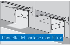
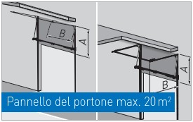
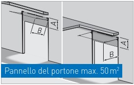
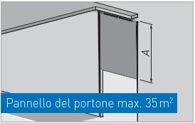
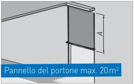
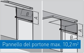
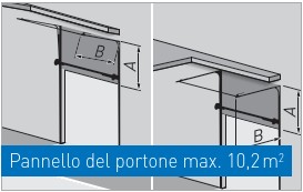
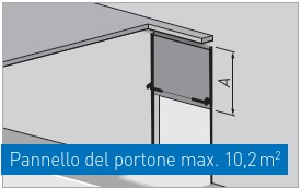
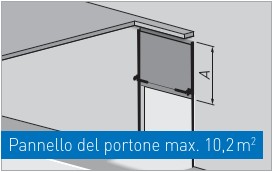
The different variants of the guide systems also allow the door to be installed in almost any application situation. The choice of configuration always depends on the site specifications and the construction possibilities of the building, which is why we offer customisable guide systems, designed to adapt precisely to each installation context.

In this section, we will clearly explain the operating principle, the main mechanisms and the range of accessories and equipment available, so that you will understand how to configure the product to suit your application requirements.

OVERVIEW OF RAIL SYSTEMS

T 240

LOWERED ARCHITRAVE SYSTEM REAR SPRINGS GROUP
A = 240 mm
B = free height + 1,000 mm
Max. width 6,500 mm

T 340

LOWERED ARCHITRAVE SYSTEM
A = 340 mm
B = free height + 750 mm
Max. width 6,500 mm

T 450

STANDARD SYSTEM
A = 430 - 510 mm
B = clear height + 650 mm

T 400 HF

PARTIALLY VERTICAL GUIDES WITH LOWERED SPRING GROUP + STEEL SUPPORT PROFILE
A = lifting system + 200 mm
B = free height - lifting + 600 mm
Width max. 4,500 mm
Lifting required min. 1,450 mm

T 400

PARTIALLY VERTICAL GUIDES
A = lifting system + 400 mm
B = free height - lifting + 600 mm

T 500

VERTICAL GUIDES
A = free height + 560 mm

T 500 HF

VERTICAL GUIDES WITH LOWERED SPRING GROUP + STEEL SUPPORT PROFILE
A = free height + 400 mm
Max. width 4,500 mm

T 400 DS

PARTIALLY VERTICAL GUIDES WITH LOWERED SPRING GROUP
A = lifting system + 200 mm
B = free height - lifting + 600 mm
Width max. 3,200 mm
Height max. 3,200 mm
Lifting required min. 1,700 mm

T 400 DDE

PARTIALLY VERTICAL GUIDES WITH LOWERED SPRING GROUP + STEEL BEARING PROFILE (PRE-MOUNTED)
(available from 9 doors)
A = lifting system + 200 mm
B = free height - lifting + 600 mm
Width max. 3,200 mm
Height max. 3,200 mm
Lifting required min. 1,700 mm

T 500 DS

VERTICAL GUIDES WITH LOWERED SPRING GROUP
A = clearance height + 400 mm
Width max. 3,200 mm
Height max. 3,200 mm

T 500 DDE

VERTICAL GUIDES WITH LOWERED SPRING GROUP + STEEL BEARING PROFILE (PRE-MOUNTED)
(available from 9 doors)
A = free height + 550 mm
Width max. 3,200 mm
Height max. 3,200 mm

RAIL SYSTEMS

The guide systems, which are modular and largely pre-assembled, can be used on both Thermo and NovoLux doors. All guide systems and suspension mechanisms are designed and assembled with construction quality and durability at their core, with solutions designed to ensure stable and reliable operation over time.

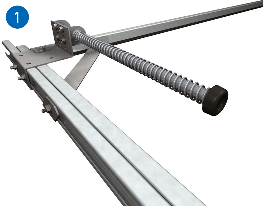
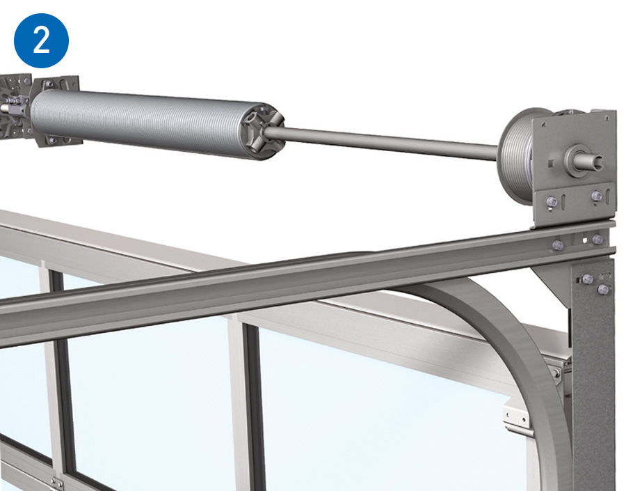
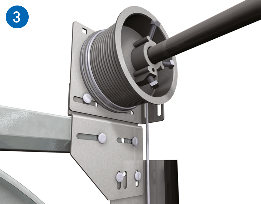
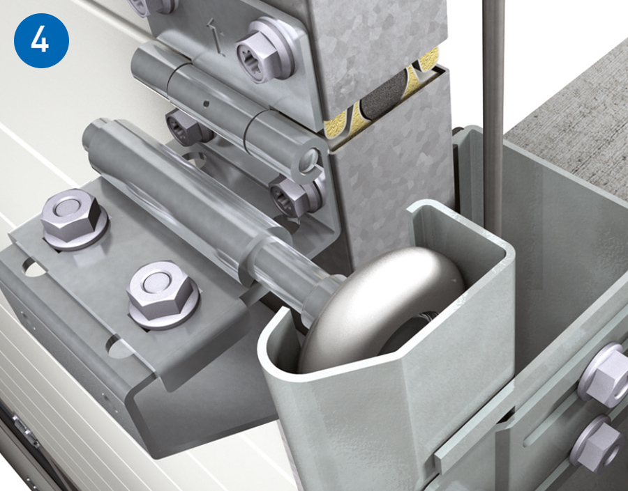
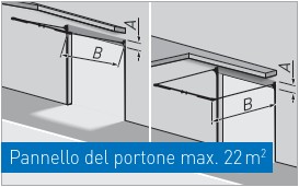
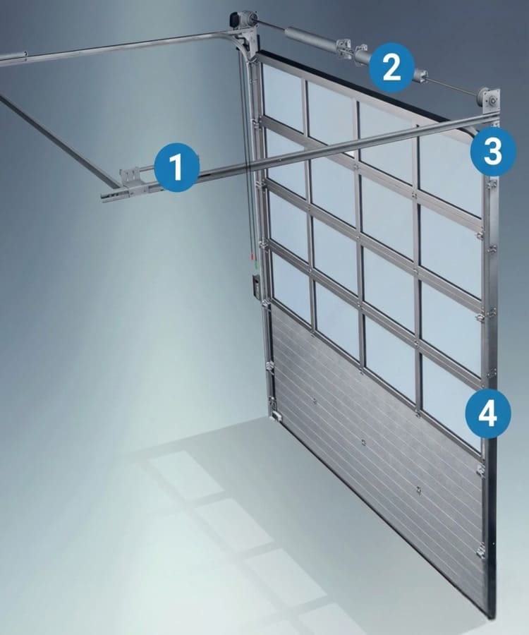
In particular, the diagram highlights:

  1. Spring buffer: ensures the correct end stop and contributes to precise and controlled closing.
  2. Torsion springs: they balance the weight of the sash, favouring smooth sliding and reducing the effort in opening and closing.
  3. Load-bearing rope: fundamental support element for movement, designed to guarantee high operational safety.
  4. Safety guides: they limit the risk of slipping and keep the sash on track, increasing stability during movement.

Below are the specifications and characteristics of each element, so you can understand how each component contributes to the safety, smoothness of movement and overall durability of the system.

SPRING BUMPER
The spring buffer, which is particularly robust, provides the door with the initial thrust required to start closing when it is in a horizontal position. Its length is dimensioned according to the specific door configuration.

TORSION SPRINGS
As standard, the torsion springs are sized for 30,000 cycles. For heavy-duty applications, an increased version designed for 60,000 cycles is available as an option to maintain the same operating efficiency over time.

SUPPORT ROPE
Thanks to the modular design of our guide and fitting systems, the support rope is always kept in the correct position in relation to the vertical guides. This helps maximise safety during door operation.

SAFETY GUIDES
The safety guide prevents the rollers from slipping. As additional protection, the rope is encapsulated and held securely inside the guide. This increases the stability of the system during handling.